How to turn on the LED indicator. What are LED indicators for? Design features and types
This is the second year I’ve been resuscitating Solntsev’s amplifier, assembled 20 years ago. One of the amplifier components is an output power indicator. At the time of creation, the amplifier included an indicator assembled on a K155LA3 - 8 housings + body kit. It worked well, but is not modern now. Reincarnation on a modern base under the cut.
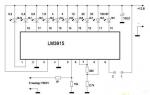
In the process of resuscitation, I decided to build a new indicator based on modern elements. The indicator circuit based on the LM3915 is currently popular. 
Unfortunately, I didn’t immediately find a line of LED indicators in one housing for sale in our area and assembled them using separate LEDs. 

Overall, it turned out well, but the blurriness (even cloudiness) of the light spots was not entirely satisfactory.
While looking for an LED strip, I came across a line of LED indicators in one housing with 12 segments, 8 of which are green and 4 red. 
In my design, 10 LEDs are used to indicate the output power of the amplifier, and two LEDs are used to indicate the presence of negative or positive voltage at the amplifier output.
Waiting for the parcel, a nominal delivery fee and alteration of the indicator did not deter me from purchasing it.
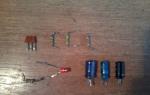
The findings of each indicator were carefully protected by the seller and packed in a bubble wrap envelope. 

The front side of each panel is covered with a protective sticker. 
The indicators are filled with a transparent compound on the inside 
In general, I was very pleasantly surprised by the quality of the indicators - not a faceless product.
The dimensions stated by the seller are exactly the same as in reality. The manufacturer did not skimp on the length of the leads.
Since the seller did not indicate either the current consumption of the LEDs or the operating voltage, he considered these data generally accepted, approximately 2 - 3 Volts, with a current of 20-30 mA.
However, I first checked the indicator LEDs with a T4 tester. 

Uf, v – voltage at which the LED starts to glow in volts,
C, pf – junction capacitance in picofarads
In the table, LEDs 1 to 8 are green, 9-12 are red.
There is some scattering of parameters, but it does not affect the work in any way.
Until the indicators arrived, I thought not to etch the new board, but to use a breadboard, but it turned out that the pitch between the pins is not 2.54 mm, but exactly 2. This can actually be seen from the drawings on the seller’s page, but such little things when buying didn't pay attention.
Having installed the metric grid in Sprint-Layout, I laid out the board. In the process, I encountered another, if not difficulty, then not standardization of the panel - the LED leads are not located in the center of the body, but are shifted to one edge - located at a distance of 1.6 mm from the center. This created a slight inconvenience - I needed to place two indicators side by side, without a gap between the housings. I had to reduce the grid pitch to 0.25 mm and print the board on paper several times, trying on the indicators.
As a result, the following board was obtained 


Comparison of results: 
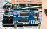
Circuit installation and testing 


The camera is a little blurry with the glow of the segments, but in real life everything looks very decent. Each LED produces its own distinct glow without creating a cotton-wool spot.
Perhaps this is a subjective feeling, but the indicator came to life, the display speed increased and became more adequate compared to the original version - a certain retardation disappeared.
I am extremely pleased with the purchase and the result obtained, despite the non-standard pitch of the leads and their displacement relative to the center of the case and can recommend this product.
In addition, the seller has a wide variety of indicators for different purposes.
Sprint fee:
In the first tab there is a board with microcircuits + an indicator board with separate LEDs. In the second tab there is a board for the monitored indicators.
I was in an electronics store the other day. Sometimes various used radio components appear in it at a low price. This time I saw the microcircuit, since it cost a penny, I bought it without hesitation. I decided to make a simple mono signal indicator. Why mono and not stereo? Because there is only one chip. I'll finish the second channel later...
Having printed the circuit using a laser printer on glossy paper, we begin to transfer the toner (ink) to the board. We do this as follows: we place the paper on a board that has been well sanded and run it over the board with a heated iron for 10 minutes. We wait until the board cools down and carefully remove the paper under hot water. It should look like this:

Then we etch the board in ferric chloride. After about an hour, my board was completely etched. Using a solvent, we get rid of the paint and use sandpaper to give the board a more rectangular appearance.

We're making payment. Then we start soldering the parts. First I soldered the chip. After the LEDs, and then the rest of the parts. Photo of the fully finished board:

Circuit operation
I’ll briefly tell you about the purposes of the parts. Using R2 we adjust the input signal level. Through capacitor C1, the signal goes to the base of transistor VT1, which serves as an amplifier. Resistor R3 sets the bias to the base of the transistor. Then the amplified signal “comes” through capacitor C2 to diodes VD1 and VD2.

The negative signal goes to the minus, the positive signal to the 5th leg of the microcircuit. C3 and R4 serve as a filter. The higher the voltage on leg 5, the more LEDs light up. By the way, if you short pin 9 to positive, the LEDs will light up linearly. In the video you can see how this thing works.
Video of LED indicator operation
Display symbols on scoreboards, electronic clocks and much more. An LED indicator is a simple design that displays alphabetic or symbolic characters. Structurally, it is an assembly of LEDs, where each element is illuminated by a sign-segment indicator.
Design features and types
LED indicators consist of integrated circuits that display various information. The operating voltage ranges from 2V to 8V. They can be:
Segmental;
- Matrix;
- Linear scale;
- Single
The first variety is used most often and is the standard type. Depending on the model, the structure can be assembled from 1-4 seven-segment groups. The size of the object and the number of displayed characters depend on their number. Thus, one seven-segment group will show only one number or letter. Four groups are used in electronic watches. When choosing a circuit for homemade use, the buyer should pay attention to the presence of a common anode and cathode.
In addition to small indicators, there are also those that can be seen in public places. To increase their brightness, sequentially connected LEDs are used, built into each individual component. In order for the indicator to show a certain number or symbol, a voltage of 11.2 Volts is applied. The elements have their own names: A, B, C, D, F or G. The operation is determined by digital shift registers and decoders.
Data encryption and integrated circuits
Such elements are installed on a board that controls the voltage supply. The work is due to access to program code and the use of special microcontrollers. Using programming, timing is set that affects the display of components at a certain time.
The integrated circuit converts the binary and binary decimal code supplied to the display. Common circuits for controlling domestic indicators are K514ID2 or K176ID2, in imported models 74HC595. Management is possible in two ways:
Directly, through microcontrollers;
- Using shift registers
The first option is less successful due to the need to connect many pins. In addition, the current consumption may be higher than is possible with microcontrollers. Large seven-segment indicators depend on the MBI5026 chip.
Features of segment indicators
In electronics they are used for visual inspection. The structure consists of the following elements:
A character-synthesizing indicator is a device in which visual information is displayed using one or more components;
- Data display field – numbers or other symbols are displayed within it;
- Display element – a structural part that has its own control;
- Segment – an element of information display, presented in the form of straight or curved lines;
- Familiar space – the space required to display one character
All electronic devices perform basic tasks:
1. Visual information.
2. They have a complete design.
3. Equipped with electronic control
Segment modifications differ from matrix modifications in that each element is unique. The shape of the characters is designed specifically to display certain numbers or symbols. The latter are based not on seven, but on nine, fourteen or sixteen segments. When the number exceeds 7, then it is quite rational to use dynamic switching indication. LED display and indication is also possible in two-color form. Light bulbs of different colors are used and connected to a common circuit. By combining the findings, a combined shade is obtained.
Conclusion
The operation of indicators is impossible without LEDs. Such devices are relevant not only for radio equipment, but are successfully used for signs, timers and indicators. Devices of various types of circuit and control can be used to display information.
Share information on your social media pages regarding this topic.
In this lesson we will learn about the diagrams for connecting seven-segment LED indicators to microcontrollers and how to control the indicators.
LED seven-segment indicators remain one of the most popular elements for displaying digital information.
Their following qualities contribute to this.
- Low price. In terms of display, there is nothing cheaper than LED digital indicators.
- Variety of sizes. The smallest and largest indicators are LED. I know of LED indicators with digit heights from 2.5 mm to 32 cm.
- Glow in the dark. In some applications this property is almost decisive.
- They have different glow colors. There are even two-color ones.
- Quite low control currents. Modern LED indicators can be connected to the pins of microcontrollers without additional keys.
- Suitable for harsh operating conditions (temperature range, high humidity, vibration, aggressive environments, etc.). For this quality, LED indicators have no equal among other types of display elements.
- Unlimited service life.
Types of LED indicators.
The seven-segment LED indicator displays a character using seven LEDs - digit segments. The eighth LED illuminates the decimal point. So there are 8 segments in a seven-segment indicator.

Segments are designated by Latin letters from “A” to “H”.
The anodes or cathodes of each LED are combined in the indicator and form a common wire. Therefore, there are indicators with a common anode and a common cathode.
LED indicator with common anode.

LED indicator with common cathode.

Static LED control.
LED indicators must be connected to the microcontroller through current-limiting resistors.

The calculation of resistors is the same as for individual LEDs.
R = (U supply - U segment) / I segment
For this circuit: I segment = (5 – 1.5) / 1000 = 3.5 mA
Modern LED indicators glow quite brightly even at a current of 1 mA. For a circuit with a common anode, the segments will light up, at the control pins of which the microcontroller will generate a low level.
In the connection diagram of an indicator with a common cathode, the polarity of the power supply and control signals changes.

The segment will light up, at the control pin of which a high level (5 V) will be generated.
Multiplexed mode for controlling LED indicators.
Eight pins are required to connect each seven-segment indicator to the microcontroller. If there are 3–4 indicators (digits), then the task becomes practically impossible. There just aren't enough microcontroller pins. In this case, the indicators can be connected in multiplexed mode, in dynamic indication mode.
The findings of the same-named segments of each indicator are combined. This results in a matrix of LEDs connected between the segment pins and the common indicator pins. Here is a circuit for multiplexed control of a three-digit indicator with a common anode.

To connect three indicators, 11 pins were required, and not 24, as in the static control mode.
With dynamic display, only one digit is lit at any time. A high-level signal (5 V) is supplied to the common pin of one of the bits, and low-level signals are sent to the segment pins for those segments that should light up in this bit. After a certain time, the next discharge is lit. A high level is applied to its common pin, and status signals for this bit are sent to the segment pins. And so on for all digits in an endless loop. The cycle time is called the indicator regeneration time. If the regeneration time is short enough, the human eye will not notice the switching of discharges. It will seem that all the discharges are constantly glowing. To avoid flickering of indicators, it is believed that the frequency of the regeneration cycle should be at least 70 Hz. I try to use at least 100 Hz.
The dynamic indication circuit for LEDs with a common cathode looks like this.

The polarity of all signals changes. Now a low level is applied to the common wire of the active discharge, and a high level is applied to the segments that should light up.
Calculation of dynamic display elements of light-emitting diode (LED) indicators.
The calculation is somewhat more complicated than for the static mode. During the calculation it is necessary to determine:
- average current of segments;
- pulse current of segments;
- segment resistor resistance;
- pulse current of the common terminals of the discharges.
Because The indicator digits light up in turn, the brightness of the glow determines the average current. We must choose it based on the indicator parameters and the required brightness. The average current will determine the brightness of the indicator at a level corresponding to static control with the same constant current.
Let's choose an average segment current of 1 mA.
Now let's calculate the pulse current of the segment. To provide the required average current, the pulse current must be N times greater. Where N is the number of indicator digits.
I segment imp. = I segment avg. *N
For our scheme I segment. imp. = 1 * 3 = 3 mA.
We calculate the resistance of the resistors that limit the current.
R = (U supply - U segment) / I segment. imp.
R = (5 – 1.5) / 0.003 = 1166 Ohm
We determine the pulse currents of the common terminals of the discharges. 8 segments can light up at the same time, which means you need to multiply the pulse current of one segment by 8.
I category imp. = I segment imp. * 8
For our circuit I category imp. = 3 * 8 = 24 mA.
- We select the resistor resistance to be 1.1 kOhm;
- the pins of the segment control microcontroller must provide a current of at least 3 mA;
- the pins of the microcontroller for selecting the indicator digit must provide a current of at least 24 mA.
With such current values, the indicator can be connected directly to the pins of the Arduino board, without using additional keys. For bright indicators, such currents are quite sufficient.
Schemes with additional keys.
If indicators require more current, then it is necessary to use additional keys, especially for digit selection signals. The total discharge current is 8 times the current of one segment.
Connection diagram for an LED indicator with a common anode in multiplexed mode with transistor switches for selecting discharges.

To select a bit in this circuit, it is necessary to generate a low-level signal. The corresponding key will open and supply power to the indicator discharge.
Connection diagram for an LED indicator with a common cathode in multiplexed mode with transistor switches for selecting discharges.

To select a bit in this circuit, it is necessary to generate a high-level signal. The corresponding key will open and close the common discharge terminal to ground.
There may be circuits in which it is necessary to use transistor switches for both segments and common bit pins. Such schemes are easily synthesized from the previous two. All shown circuits are used when the indicator is powered with a voltage equal to the microcontroller power supply.
Keys for indicators with increased supply voltage.
There are large indicators in which each segment consists of several LEDs connected in series. To power such indicators, a source with a voltage greater than 5 V is required. The switches must provide switching of increased voltage controlled by microcontroller level signals (usually 5 V).
The circuit of keys that connect the indicator signals to ground remains unchanged. And the power switches should be built according to a different scheme, for example, like this.

In this circuit, the active bit is selected by the high level of the control signal.
Between switching indicator digits, all segments should be turned off for a short time (1-5 μs). This time is necessary to complete the transient processes of key switching.
Structurally, the discharge pins can be combined in one case of a multi-digit indicator, or a multi-digit indicator can be assembled from separate single-digit indicators. Moreover, you can assemble an indicator from individual LEDs combined into segments. This is usually done when it is necessary to assemble a very large indicator. All the above schemes will be valid for such options.
In the next lesson, we will connect a seven-segment LED indicator to the Arduino board and write a library to control it.
Category: . You can bookmark it.This article continues the series of my publications about the organization of dynamic indication on PIC microcontrollers and LED indicators. Here are links to previous posts:
Table of operation of the proposed algorithm (an indicator with a common cathode is used, the first column shows the register outputs combined with the indicator digits) according to the connection diagram given below.
In each of the interrupts with an interval of 2 ms (in this case from the TMR0 timer), one stage of dynamic indication (DI) is prepared according to an algorithm that consists of five phases of register and indicator control.
2nd phase: The positive edge at pin 12 of the register (ST_CP) writes the zero state of the register to the output latch. Here and further, before the start of the indication, the indicator is extinguished by zero potential on the segments.
3rd phase: by controlling register pins 14 (DS - data) and 11 (SH_CP - clock), the code for controlling the segments is written into it.
4th phase: with a positive drop at pin 12 of the register, data from the register is written to the output latch, and, due to the positive levels on the bits, the indicator remains off.
5th phase: here the required code is supplied to the outputs of the indicator digits, and then the actual indication occurs.
If the circuit uses one 4-digit indicator, then for proper operation it must be set to OK. If you need to control 8 bits, then 8 ports of the MK are used, while the remaining 4 ports simply control the bits (in phase 4 they should have a high level). It is worth noting that in this case it is possible to use indicators with both OK and OA, connecting segments or digits to the register, respectively (for the reasons stated below, in the first case it is preferable to organize DI segment-by-segment, and in the second - bit-by-bit).
Using this method, you can connect two four-bit indicators to the PIC16F676 MCU using one shift register, while leaving as many as four free ports for use. For example, for such a connection, people used the combination of DI and analog input functions in some MK ports (in my opinion, an extremely dubious decision), which led to a significant complication of the circuit and to some limitations, which the authors warn about. Using my connection diagram, everything would be solved simply and beautifully - separate inputs, separate indications, plus two more ports (including MCLR) for buttons.
To test this control method, the following simple circuit is proposed on the PIC12F629 MCU and the FYQ3641A indicator, which alternately displays the word “test” and the number 1234 on the indicator.

Here it was decided to use a segment-by-segment DI (one segment is turned on at each moment, and there is a code on the bit pins, where in each bit: 0 - if this segment should be lit in a given bit and 1 - otherwise), in which peak currents are transferred to the register . Why? There are two reasons for this: the first is the maximum load capacity of the 74HC595 outputs 35 mA versus 25 mA for PIC controllers; the second and main thing is that a current close to the limit through the output port of the MK can theoretically raise its output potential to the level of switching the register inputs, which would lead to errors in operation. And so, currents of 6-7 mA flow into the MK ports and the potentials at the outputs certainly do not exceed TTL levels.
As mentioned above, the interruption interval is 2 ms, which corresponds to the indicator refresh rate of 64 Hz and its glow is quite comfortable for the eye.
This DI method, among other things, made it possible to halve the number of current-limiting resistors (R2-R5).
The device is assembled on a so-called “solderless” breadboard.

The indicator can be replaced with any of the 3641A series.
The circuit is powered by a stabilized 5 V source. I used a special stabilizer board designed for use with the breadboard mentioned above.
The MK control program is written in C language and translated in the environment.
Code in MikroC, project, HEX file in the application.
To use this connection method in commercial developments, please contact me.
List of radioelements
| Designation | Type | Denomination | Quantity | Note | Shop | My notepad |
|---|---|---|---|---|---|---|
| DD1 | MK PIC 8-bit | PIC12F629 | 1 | To notepad | ||
| DD2 | Register | 74HC595 | 1 | To notepad | ||
| H.L. | Indicator | FYQ3641 | 1 | To notepad | ||
| R1 | Resistor | 30 kOhm | 1 | To notepad | ||
| R2 | Resistor | 430 Ohm | 1 | To notepad | ||
| R3 | Resistor | 430 Ohm | 1 |