Drawings, designs, ideas. Microphone amplifier on a microcircuit Microphone amplifier on transistors with your own hands
Hello! In this article I want to tell you about a microphone preamp.
From the very title of the article it is clear that we will strengthen something. First, let's look at one example. You connected a dynamic microphone to your computer and decided to record your voice. But apart from very quiet speech, filled with a lot of noise and interference, you heard nothing. And all because 1.5 V appears at the input of the computer’s audio card. This very one and a half volts presses the coil inside the microphone, and when you speak, they prevent it from moving. This means that this voltage needs to be somehow removed and the signal strengthened. For this we will make a pre-amplifier. That is, the sound from the microphone will enter the computer already amplified and without noise.
So, let's get started.
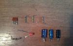
To do this you need the following components:
Resistors – 4.7 kOhm – 2 pcs., 470 kOhm, 100 kOhm.
Capacitors – 4.7 µF, 10 µF, 100 µF.
Transistor– KT315.
Light-emitting diode – not necessary.
Tools:
Soldering iron, wire cutters, tweezers, scissors, glue gun, etc..

Let's start production.
1.
First, let's look at the diagram and details.
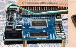
Resistor R5 put for electret microphone and acts as a voltage bias. We don't use it. The KT315 transistor can be replaced with KT3102, BC847. KT3102 has a higher gain, so it is preferable to install it. LED is optional. If it is not needed, replace it with a diode. I found a piece of a homemade breadboard at my place. I will make a diagram on it.

2. Now, according to the diagram, solder all the components.


3. Next, we solder the power connectors, microphone input and output, and power switch. 6.3 mm jack connector. I took a 3.5 mm jack from an old DVD player. - from a tape recorder. A connector for a battery from a non-working crown, a switch from a toy car. Solder everything to the board.


There is no LED in the photo; it appeared later.
4. Now let's take care of the body. I found some kind of plastic box without a bottom. She just fit all the details. We drill holes in it for connectors, an LED, and cut out a rectangular hole for a switch.


5. Now we assemble everything into the case. We glue the crown and board with double-sided tape, and the connectors with hot-melt adhesive.

The bottom was made of durable black cardboard.
6. Check. I had the cheapest BBK karaoke microphone. I connected it. Next, using a jack-jack wire, we connect the amplifier output to the computer, speakers, or whatever you need. Turn on the power. The LED lit up. The preamp is working.


Microphone preamp, also known as a pre-amplifier or amplifier for a microphone, is a type of amplifier whose purpose is to amplify a weak signal to a linear level (about 0.5-1.5 volts), that is, to an acceptable value at which conventional audio power amplifiers operate .
The input source of acoustic signals for a preamplifier is usually vinyl record pickups, microphones, and pickups of various musical instruments. Below are three circuits of microphone amplifiers on transistors, as well as a variant of a microphone amplifier on the 4558 chip. All of them can be easily assembled with your own hands.
Circuit of a simple microphone preamplifier using one transistor
This microphone preamplifier circuit works with both dynamic and electret microphones.
Dynamic microphones are similar in design to loudspeakers. The acoustic wave affects the membrane and the acoustic coil attached to it. When the membrane oscillates, an electric current is generated in a coil exposed to the magnetic field of a permanent magnet.
The operation of electret microphones is based on the ability of certain types of materials with increased dielectric constant (electrets) to change the surface charge under the influence of an acoustic wave. This type of microphone differs from dynamic microphones in its high input impedance.
When using an electret microphone, to bias the voltage on the microphone, it is necessary to set the resistance R1
single transistor microphone amplifier
Since this microphone amplifier circuit is for a dynamic microphone, when using an electrodynamic microphone, its resistance should be in the range from 200 to 600 Ohms. In this case, C1 must be set to 10 microfarads. If it is an electrolytic capacitor, then its positive terminal must be connected towards the transistor.
Power is supplied from the crown battery or from a stabilized power source. Although it is better to use a battery to eliminate noise. can be replaced with a domestic one. Electrolytic capacitors for a voltage of 16 volts. To prevent interference, connect the preamplifier to the signal source and to the amplifier input using a shielded wire. If further powerful sound amplification is needed, then you can assemble an amplifier on a microcircuit.
Microphone preamplifier with 2 transistors
The structure of any preamplifier greatly affects its noise characteristics. If we take into account the fact that the high-quality radio components used in the preamplifier circuit still lead to distortion (noise) to one degree or another, then it is obvious that the only way to get a more or less high-quality microphone amplifier is to reduce the number of radio components in the circuit. An example is the following two-stage preliminary circuit.

With this option, the number of decoupling capacitors is minimized, since the transistors are connected in a circuit with a common emitter. There is also a direct connection between the cascades. To stabilize the operating mode of the circuit when the external temperature and supply voltage change, a direct current feedback loop has been added to the circuit.
Preamplifier for electret microphone with three transistors
This is another option. The peculiarity of this microphone amplifier circuit is that power is supplied to the preamplifier circuit through the same conductor (phantom power) through which the input signal travels.

This microphone preamplifier is designed to work together with, for example, MKE-3. The supply voltage to the microphone goes through resistance R1. The audio signal from the microphone output is supplied to the VT1 base through capacitor C1. , consisting of resistances R2, R3, creates the necessary bias at the base of VT1 (approximately 0.6 V). The amplified signal from resistor R5, acting as a load, goes to the base of VT2 which is part of the emitter follower on VT2 and VT3.
Near the output connector, two additional elements are installed: load resistor R6, through which power is supplied, and separating capacitor SZ, which separates the output audio signal from the supply voltage.
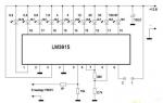
Pre-microphone amplifier based on 4558 chip
The 4558 operational amplifier is manufactured by ROHM. It is characterized as a low power and low noise amplifier. This microcircuit is used in a microphone amplifier, audio amplifiers, active filters, and voltage-controlled generators. The 4558 chip has internal phase compensation, increased input voltage threshold, high gain and low noise. This op amp also has short circuit protection.

(140.5 Kb, downloads: 2,161)

microphone preamplifier for 4558
This is a good option for building a microphone preamp on a chip. The microphone preamplifier circuit is characterized by high amplification quality, simplicity and does not require much wiring. This dynamic microphone amplifier also works well with electret microphones.
With error-free assembly, the circuit does not require configuration and starts working immediately. The highest current consumption is 9 mA, and at rest the current consumption is around 3 mA.
A simple DIY microphone amplifier for a computer
This article is about the design of a simple microphone amplifier that can be used to amplify the signal of an electret or dynamic microphone.
With a minimum number of parts, such an amplifier allows you to improve the signal-to-noise ratio and increase the microphone signal gain compared to the amplifier of the built-in audio card. https://site/
I'm about to record my first video lesson. Already made it. But the very first attempt to record a voice stumbled over incredibly high noise and insufficient gain of the microphone amplifier of the built-in audio card.
The most interesting videos on Youtube
By turning off the Microphone Boost mode, it was possible to reduce the noise, but the gain level became so low that it became impossible to record anything.
I had already decided to buy a separate audio card, but I discovered that a good audio card is very expensive, and a budget one for $10, although it has a lower noise level, also has a microphone amplifier with a not very high gain.
So, I set about making a simple microphone amplifier.

The first experiments with prototypes of microphone amplifiers showed that the noise level can be reduced and the gain increased.
One can only wonder how computer hardware developers manage to produce such “pearls”, while just a few cheap parts solve the problem of noise and amplification.
Construction and details.
When choosing an amplifier circuit, I focused mainly on ease of operation and the minimum number of parts spent on construction. The goal was not to produce a super-duper amplifier with record performance.
After prototyping several circuits on Sovdepov microcircuits, I settled on the K538UN3A (KR538UN3A) chip. https://site/
The reasons are as follows:
Why DL123A (CR-P2)? Due to the toxic filling, the cases of these elements are made of stainless steel and carefully sealed, which prevents the destruction of the case and damage to the amplifier circuit. The latter often happens when using salt and alkaline (alkaline) elements. (The GP alkaline elements damaged my beloved Maglite).
Technical parameters of K538UN3A.
Below I publish technical data taken from a paper reference book on analog microcircuits, since I did not find detailed information about this microcircuit on the Internet.
The microcircuit is an ultra-low-noise broadband signal amplifier with a frequency of up to 3 MHz. The amplifier's noise characteristics are optimized for operation with low-impedance signal generators. The gain is fixed by the internal divider, but it can be adjusted externally. The amplifier is intended for use as a playback pre-amplifier in high-end equipment, as well as an amplifier for low-impedance sensors. Housing 2101.8-1 (DIP8) or 301.8-2.
Electrical parameters.
Rated supply voltage – +6V.
Current consumption at Up = 6V, T = -45… +70C, no more than – 5mA.
Voltage amplification factor with internal feedback at Up = 6V, f = 1 MHz, Uin. = 1mV, Rn = 10kOhm, T = +25C:
no less than 200,
no more than 300,
typical value is 250.
Voltage amplification factor without internal feedback at Up = 6V, f = 1 MHz, Uin = 1 mV, Rn = 10 kOhm, T = +25 C, typical value – 3000.
Normalized voltage of self-noise at Up = 6V, f = 1 MHz, Uin = 1 mV, Rg = 500 Ohm, Rn. = 10kOhm, T = +25C, no more than – 5nV/√Hz, typical value – 2.1nV/√Hz.
Maximum output voltage Up = 6V, Rn = 2kOhm, Kg = ≤ 10%, T = -45C, not less than 0.5V, typical value – 1V.
Upper cutoff frequency at Up = 6V, Rn = 2 kOhm, Ku = 100, T = +25C, typical value – 3 MHz.
Input impedance – 10 kOhm.
Limit operating data.
The maximum supply voltage is 7.5V.
The maximum input voltage is 200mV.
Minimum load resistance (short-term) – 0 Ohm.
Ambient temperature, long-term exposure: –45… +70С, short-term exposure: –60… +125С.
Pin assignment of the K538UN3A microcircuit.

Housing 2101.8-1.
- Nutrition.
- Not used.
- Correction.
- Entrance.
- Gain adjustment pin.
- Connecting the OS DC filter.
- General.
- Exit.

Housing 301.8-2.
A somewhat outdated version of the microcircuit.
Typical circuit diagram for connecting a microcircuit.

- C2 – power filter.
- C5 – separating.
- C6 – corrective.
- C8 – DC filter.
- R4 – adjustment of operating system for alternating current.

The presented microphone amplifier circuit can amplify the signal of both an electret and a dynamic microphone.
The value of resistor R4 determines the gain of the DA1 chip.
The maximum gain is achieved at R4 = 0.
To quickly adjust and limit the input signal level during overload, potentiometer R3 is used.
Resistor R2, diode VD2 and LED HL1 represent a voltage divider on which 2.2V is generated to power the electret microphone. Resistor R1 is the load of the electret microphone. The HL1 LED also functions as a power indicator.

The circuit can be significantly simplified if you rely only on the use of a dynamic microphone. You just need to keep in mind that when using a passive dynamic microphone with low sensitivity, you may need to increase the gain, which will lead to a slight increase in the noise level of the microphone amplifier.
Printed circuit boards.
The images of printed circuit boards show a view from the side of the elements. The tracks are visible through the board.

The picture shows an example of the PCB layout of a universal microphone amplifier.
- Entrance.
- The top end of potentiometer R3 according to the diagram.
- Potentiometer motor R3.
- LED anode HL1.
- Frame.
- Power supply +6V.
- Exit.
- Frame.

An example of a printed circuit board layout for a dynamic microphone amplifier.
- Entrance.
- Frame.
- Power supply +6V.
- Exit.
- Frame.
I myself made a printed circuit board based on the dimensions of the controls and housing at my disposal.
Frame.

It would be good to choose a metal case to house the structure. If a plastic case is used, then it is advisable to place the entire structure in the screen. The screen can be made from the tin of a condensed milk can. These cans are still tin plated and they solder just fine (they don't even need to be tinned). Both tasty and healthy... for the homemade person. The housing of the signal level control must be connected to the shield of the entire amplifier.

The picture shows a duralumin housing and a printed circuit board assembly. The board has two independent amplifiers with separate power management. To be able to record a stereo signal using two arbitrary microphones, the amplifier of each channel is equipped with a separate input jack.
Control elements are installed directly on the printed circuit board. Gain adjustment is carried out once by selecting fixed resistors when setting up the amplifier.

Microphone amplifier assembly. The microphone amplifier is connected to the computer using a shielded cable, at the end of which there is a 3.5mm Jack connector.
Comparative tests.
During the comparative test, the controls were set to a position that would ensure the same level of the recorded signal, both with and without a microphone amplifier.
Green - noise level.
Raspberry is a type of noise.

The graph shows the noise level of the microphone amplifier of the built-in audio card in the “Microphone Boost” mode.
Recording level is 1.0.
The noise level is about -80dB.

In order to obtain a minimum noise level, I set the maximum signal level with resistor R3. This made it possible to use the audio card's line-in amplifier with a low gain level.
This graph shows the noise level of a homemade microphone amplifier.
Recording level 0.05.
The noise level is about -110dB.

Audio cart drivers usually do not allow you to set the recording level with such high precision.
You can set the recording level with an accuracy of a fraction of a percent using the free portable audio editor Audacity, a link to which is in the “Additional Materials”.
The recording or broadcasting of sound itself can be done using any other programs.
How to properly connect a dynamic microphone to a cable.
Having a stereo microphone from an old reel-to-reel tape recorder, I wanted to record stereo sound. But it was not there…
The sensitivity of dynamic microphones is inferior to that of electret microphones, which places increased demands on the former for shielding from interference and interference. However, these requirements are often ignored by the manufacturer. This was exactly the case with my microphones. They were connected to the cable in different ways, but each was incorrect in its own way.

- Frame.
- Coil output.
- Coil output.
The figure shows that the left microphone had no housing connected at all, while the right one had one of the coil terminals connected to the housing. Both of these connections were made incorrectly, especially considering that a shielded twisted pair cable was used.

The picture shows how to properly connect a dynamic microphone to a microphone amplifier with an asymmetrical input.

And this is connecting a microphone to a microphone amplifier with a balanced input.

The cheapest dynamic microphones are connected using a single-wire shielded cable. The figure shows a diagram of such a connection.
If you hear interference in the form of background with a frequency of 50 Hz, then it is better to connect the microphone using shielded twisted pair cable.
The dotted line in the diagrams shows the metal body of the microphone, which should be connected to the braided shielding cable. The coil terminals must be connected to a twisted pair. Not all budget dynamic microphones allow you to do this painlessly. Often one of the coil wires is already connected to the metal body of the microphone.
Do not try to solder the coil wire to another contact yourself. The coil is wound with wire 0.05 mm or thinner. For comparison, the thickness of a human hair is 0.03-0.04mm. Any careless touching of the coil leads will inevitably lead to a break. In addition, the coil terminals are additionally coated with glue, which also complicates the task.
Hooray! It's working!
| Get the Flash Player to see this player. |
A five-second stereo recording made using two dynamic microphones and a homemade microphone amplifier. (You need to click on the picture).
The value of the resistor in the feedback circuit R4 = 50 Ohms.
The microphone amplifier signal level is maximum.
Recording level at the linear input of the audio card = 0.2.
To assemble the sensitive microphone circuit we will need:
1. Transistor BC547 or KT3102, you can try KT315.2. Resistors R1 and R2 with a nominal value of 1 kOhm. To increase the sensitivity of R1 for the capsule, rated from 0.5 - 10 kOhm.
4. Disc ceramic capacitor with a nominal value of 100-300 pF. It can be omitted if initially there are no “spikes” or excitations of the amplifier.
5. Electrolytic capacitor 5-100 µF (6.3 -16 V).
First of all, let's determine the polarity of connecting the microphone capsule. This is done simply: the minus is always connected to the body. Then we assemble the circuit, either by surface mounting or on a mini-board. The entire sensitivity of the preamplifier will depend on the gain of the transistor and the selected resistor R1. Usually the amplifier is assembled and works immediately; its sensitivity should be sufficient with a reserve.
The recording was made using a capsule without a preamplifier circuit.

The recording was made on a capsule from a pre-amplifier circuit.

The difference is visible to the naked eye. Now you don’t have to hang a microphone around your neck and shout into it. You can easily put it on the table and speak without any extra effort. Well, if the sensitivity turns out to be too high, then you can always reduce it without any problems using the settings in the operating system.
The INA217 is designed specifically for use in high-quality studio microphone preamplifiers and features low distortion and low noise amplifier input paths. The device is ideal for weak audio sources such as low impedance microphones. And many industrial, measuring and medical devices also use it due to its low noise level and wide bandwidth. A unique feature of the circuit is that it reduces signal distortion to very low levels, even at high gain.

PR1 regulator - adjusts sound gain. The table of the dependence of the gain on its resistance and the block diagram are shown below:

The microcircuit requires bipolar power supply +/-15 V DC. Ipot: 10 mA. More details about the electrical power parameters of the INA217 -

Another feature of the chip is its differential input signal, which, along with low noise and distortion, provides excellent performance in professional microphone amplifiers. Gain unevenness (imbalance) is reduced to virtually zero. The OPA2137 operational amplifier is used as feedback to eliminate the offset voltage. Phantom power is not included in the diagram itself and is drawn for reference only. INA217 retails from $5.