Eccentric clamp. Eccentric clamps Clamping force calculation
Eccentric clamps are easy to manufacture and for this reason they are widely used in machine tools. The use of eccentric clamps can significantly reduce the time for clamping a workpiece, but the clamping force is inferior to threaded clamps.
Eccentric clamps are made in combination with and without clamps.
Consider an eccentric clamp with a clamp.
Eccentric clamps cannot work with significant tolerance deviations (±δ) of the workpiece. For large tolerance deviations, the clamp requires constant adjustment with screw 1.
| Eccentric calculation |
 The materials used for the manufacture of the eccentric are U7A, U8A With
heat treatment to HR from 50....55 units, steel 20X with carburization to a depth of 0.8... 1.2 With hardening HR from 55...60 units.
The materials used for the manufacture of the eccentric are U7A, U8A With
heat treatment to HR from 50....55 units, steel 20X with carburization to a depth of 0.8... 1.2 With hardening HR from 55...60 units.
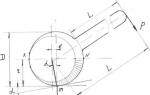
Let's look at the eccentric diagram. The KN line divides the eccentric into two? symmetrical halves consisting, as it were, of 2 x wedges screwed onto the “initial circle”.
The eccentric rotation axis is shifted relative to its geometric axis by the amount of eccentricity “e”.
Section Nm of the lower wedge is usually used for clamping.
Considering the mechanism as a combined one consisting of a lever L and a wedge with friction on two surfaces on the axis and point “m” (clamping point), we obtain a force relationship for calculating the clamping force.

where Q is the clamping force
P - force on the handle
L - handle shoulder
r - distance from the eccentric rotation axis to the point of contact With
workpiece
α - angle of rise of the curve
α 1 - friction angle between the eccentric and the workpiece
α 2 - friction angle on the eccentric axis
To avoid the eccentric moving away during operation, it is necessary to observe the condition of self-braking of the eccentric

 where α -
sliding friction angle at the point of contact with the workpiece ø -
friction coefficient
where α -
sliding friction angle at the point of contact with the workpiece ø -
friction coefficient
For approximate calculations of Q - 12P, consider the diagram of a double-sided clamp with an eccentric
 |
Wedge clamps
Wedge clamping devices are widely used in machine tools. Their main element is one, two and three bevel wedges. The use of such elements is due to the simplicity and compactness of the designs, speed of action and reliability in operation, the possibility of using them as a clamping element acting directly on the workpiece being fixed, and as an intermediate link, for example, an amplifier link in other clamping devices. Typically self-braking wedges are used. The condition for self-braking of a single-bevel wedge is expressed by the dependence
α > 2ρ
Where α - wedge angle
ρ - the angle of friction on the surfaces G and H of contact between the wedge and the mating parts.

Self-braking is ensured at angle α = 12°, however, to prevent vibrations and load fluctuations during the use of the clamp from weakening the workpiece, wedges with an angle α are often used<12°.
Due to the fact that decreasing the angle leads to increased
self-braking properties of the wedge, it is necessary when designing the drive to the wedge mechanism to provide devices that facilitate the removal of the wedge from the working state, since releasing a loaded wedge is more difficult than bringing it into the working state.

This can be achieved by connecting the actuator rod to a wedge. When rod 1 moves to the left, it passes path “1” to idle, and then, hitting pin 2, pressed into wedge 3, pushes the latter out. When the rod moves back, it also pushes the wedge into the working position by hitting the pin. This should be taken into account in cases where the wedge mechanism is driven by a pneumatic or hydraulic drive. Then, to ensure reliable operation of the mechanism, different pressures of liquid or compressed air should be created on different sides of the drive piston. This difference when using pneumatic actuators can be achieved by using a pressure reducing valve in one of the tubes supplying air or liquid to the cylinder. In cases where self-braking is not required, it is advisable to use rollers on the contact surfaces of the wedge with the mating parts of the device, thereby facilitating the insertion of the wedge into its original position. In these cases, it is necessary to lock the wedge.
Good day to lovers of homemade devices. When you don’t have a vice at hand or simply don’t have one, the easiest solution would be to assemble something similar yourself, since you don’t need any special skills or hard-to-find materials to assemble the clamp. In this article I will tell you how to make a wooden clamp.
In order to assemble your clamp, you need to find a strong type of wood so that it can withstand heavy loads. In this case, an oak plank will work well.
To begin the manufacturing phase necessary:
*Bolt, the size of which is best taken around 12-14mm.
*Nut for bolt.
*Whetstones made of oak wood.
*Part of the profile is made of wood with a cross-section of 15mm.
*Carpenter glue or parquet glue.
*Epoxy.
*Varnish, can be replaced with stain.
*Metal rod 3 mm.
*Small diameter drill.
*Chisel or chisel.
*Hacksaw for wood.
*Hammer.
*Electric drill.
*Medium grit sandpaper.
*Vise and clamp.
First step. Depending on your requests, the size of the clamp can be made different; in this case, the author cuts out blocks measuring 3.5 x 3 x 3.5 cm - one piece and 1.8 x 3 x 7.5 cm - two pieces.

After this, we clamp a 75mm long block in a vice and drill a hole using a drill, stepping back 1-2cm from the edge.

Next, match the hole you just made with the hole in the nut and trace the outline with a pencil. After marking, armed with a chisel and hammer, cut out a hexagonal countersunk for the nut.


Second step. To secure the nut in the block, you need to coat the machined groove with epoxy resin inside and immerse the same nut there, drowning it a little in the block.


As a rule, complete drying of the epoxy resin is achieved after 24 hours, after which you can proceed to the next stage of assembly.
Third step. The bolt, which ideally fits our fixed nut in the beam, needs to be modified; to do this, take a drill and drill a hole close to its hexagonal head.

After this, we move on to the bars, they need to be combined together so that there are longer bars on the sides, and a shorter bar between them. Before the three beams are clamped together, you need to drill holes at the fastening point with a thin drill so that the workpiece does not split, because this arrangement is not suitable for us.

Using a screwdriver, we tighten the screws into the prepared drilling places, having previously coated the joints with glue.


We secure the almost finished clamping mechanism with a clamp and wait for the glue to dry. For convenient use of the clamp, you need a lever with which you can clamp your workpieces; they will serve as a metal rod and a round piece of wood with a cross-section of 15 mm sawn into two parts; in both you need to drill a hole for the rod and put it all on glue.


The final stage. To complete the assembly you will need varnish or stain, we sand our homemade clamp, and then coat it with several layers of varnish.

At this point, making your own clamp is ready and it will go into working condition when the varnish is completely dry, after which you can work with this device with complete confidence.
Easy to manufacture, with a high gain, a fairly compact eccentric clamp, which is a type of cam mechanisms, has another, undoubtedly, main advantage...
... – instantaneous performance. If in order to “turn on and off” a screw clamp it is often necessary to make at least a couple of turns in one direction and then in the other, then when using an eccentric clamp it is enough to turn the handle only a quarter turn. Of course, they are superior to eccentric ones in terms of clamping force and working stroke, but with a constant thickness of the fastened parts in mass production, the use of eccentrics is extremely convenient and effective. The widespread use of eccentric clamps, for example, in stocks for assembling and welding small-sized metal structures and elements of non-standard equipment, significantly increases labor productivity.
The working surface of the cam is most often made in the form of a cylinder with a circle or Archimedes spiral at the base. Later in the article we will talk about the more common and more technologically advanced round eccentric clamp.
The dimensions of eccentric round cams for machine tools are standardized in GOST 9061-68*. The eccentricity of the round cams in this document is set to 1/20 of the outer diameter to ensure self-braking conditions over the entire operating range of rotation angles at a friction coefficient of 0.1 or more.
The figure below shows the geometric diagram of the clamping mechanism. The fixed part is pressed against the supporting surface as a result of turning the eccentric handle counterclockwise around an axis rigidly fixed relative to the support.

The position of the mechanism shown is characterized by the maximum possible angle α , while the straight line passing through the axis of rotation and the center of the eccentric circle is perpendicular to the straight line drawn through the point of contact of the part with the cam and the center point of the outer circle.
If you turn the cam 90˚ clockwise relative to the position shown in the diagram, then a gap is formed between the part and the working surface of the eccentric equal in magnitude to the eccentricity e. This clearance is necessary for free installation and removal of the part.
Program in MS Excel:
In the example shown in the screenshot, based on the given dimensions of the eccentric and the force applied to the handle, the mounting size from the axis of rotation of the cam to the supporting surface is determined, taking into account the thickness of the part, the self-braking condition is checked, the clamping force and the force transfer coefficient are calculated.
The value of the friction coefficient “part - eccentric” corresponds to the case “steel on steel without lubrication”. The value of the friction coefficient “axle - eccentric” is selected for the “steel on steel with lubrication” option. Reducing friction in both places increases the power efficiency of the mechanism, but reducing friction in the area of contact between the part and the cam leads to the disappearance of self-braking.

Algorithm:
9. φ 1 =arctg (f 1 )
10. φ 2 =arctg (f 2 )
11. α =arctg (2*e /D )
12. R =D/ (2*cos (α ))
13. A =s +R *cos (α )
14. e ≤ R*f 1+ (d/2)* f 2
If the condition is met, self-braking is ensured.
15. F = P * L * cos(α )/(R * tg(α +φ 1 )+(d /2)* tg(φ 2 ))
1 6 . k = F/P
Conclusion.
The position of the eccentric clamp chosen for calculations and shown in the diagram is the most “unfavorable” from the point of view of self-braking and gain in strength. But this choice is not accidental. If in such a working position the calculated power and geometric parameters satisfy the designer, then in any other positions the eccentric clamp will have an even greater force transmission coefficient and better self-braking conditions.
When designing, moving away from the considered position towards reducing the size A if other dimensions are kept unchanged, it will reduce the gap for installing the part.
Increase in size A can create a situation where the eccentric wears out during operation and significant fluctuations in thickness s, when it is simply impossible to clamp the part.
The article has deliberately not mentioned anything so far about the materials from which the cams can be made. GOST 9061-68 recommends using wear-resistant surface-cemented steel 20X to increase durability. But in practice, an eccentric clamp is made from a wide variety of materials, depending on the purpose, operating conditions and available technological capabilities. The above calculation in Excel allows you to determine the parameters of clamps for cams made of any materials, just remember to change the values of the friction coefficients in the initial data.
If the article turned out to be useful to you, and the calculation is necessary, you can support the development of the blog by transferring a small amount to any (depending on the currency) of the specified wallets WebMoney: R377458087550, E254476446136, Z246356405801.
Respecting the author's workI beg download file with calculation programafter subscription to article announcements in the window located at the end of the article or in the window at the top of the page!
The eccentric clamp is an improved design clamping element. Eccentric clamps (ECC) are used for direct clamping of workpieces and in complex clamping systems.
Manual screw clamps are simple in design, but have a significant drawback - to secure the part, the worker must perform a large number of rotational movements with a key, which requires additional time and effort and, as a result, reduces labor productivity.
The above considerations force, where possible, to replace manual screw clamps with quick-release clamps.
The most widespread are also.
Although it is fast-acting, it does not provide high clamping force on the part, so it is used only for relatively small cutting forces.
Advantages:
- simplicity and compactness of design;
- widespread use of standardized parts in the design;
- ease of setup;
- ability to self-braking;
- speed (drive response time is about 0.04 min).
Flaws:
- the concentrated nature of the forces, which does not allow the use of eccentric mechanisms for securing non-rigid workpieces;
- the clamping forces with round eccentric cams are unstable and significantly depend on the size of the workpieces;
- reduced reliability due to intensive wear of the eccentric cams.
Rice. 113. Eccentric clamp: a - the part is not clamped; b - position with clamped part
Eccentric Clamp Design
Round eccentric 1, which is a disk with a hole offset relative to its center, is shown in Fig. 113, a. The eccentric is freely mounted on axis 2 and can rotate around it. The distance e between the center C of disk 1 and the center O of the axis is called eccentricity.
A handle 3 is attached to the eccentric, by turning which the part is clamped at point A (Fig. 113, b). From this figure it can be seen that the eccentric works like a curved wedge (see shaded area). To prevent the eccentrics from moving away after clamping, they must be self-braking. The self-braking property of eccentrics is ensured by the correct choice of the ratio of the diameter D of the eccentric to its eccentricity e. The ratio D/e is called the eccentric characteristic.
With a friction coefficient f = 0.1 (friction angle 5°43"), the eccentric characteristic should be D/e ≥ 20, and with a friction coefficient f = 0.15 (friction angle 8°30") D/e ≥ 14.
Thus, all eccentric clamps, whose diameter D is 14 times greater than the eccentricity e, have the property of self-braking, i.e., they provide reliable clamping.

Figure 5.5 - Schemes for calculating eccentric cams: a – round, non-standard; b- made according to the Archimedes spiral.
Eccentric clamping mechanisms include eccentric cams, supports for them, trunnions, handles and other elements. There are three types of eccentric cams: round with a cylindrical working surface; curved, the working surfaces of which are outlined along an Archimedes spiral (less often - along an involute or logarithmic spiral); end
Round eccentrics
Due to ease of manufacture, round eccentrics are most widespread.
A round eccentric (in accordance with Figure 5.5a) is a disk or roller rotated around an axis displaced relative to the geometric axis of the eccentric by an amount A, called eccentricity.
Curvilinear eccentric cams (in accordance with Figure 5.5b) compared to round ones provide stable clamping force and a larger (up to 150°) rotation angle.
Cam materials
Eccentric cams are made of steel 20X, carburized to a depth of 0.8...1.2 mm and hardened to a hardness of HRCe 55-61.
Eccentric cams are distinguished by the following designs: round eccentric (GOST 9061-68), eccentric (GOST 12189-66), double eccentric (GOST 12190-66), eccentric forked (GOST 12191-66), eccentric double-bearing (GOST 12468-67) .
The practical use of eccentric mechanisms in various clamping devices is shown in Figure 5.7

Figure 5.7 - Types of eccentric clamping mechanisms
Calculation of eccentric clamps
The initial data for determining the geometric parameters of the eccentrics are: tolerance δ of the size of the workpiece from its mounting base to the place where the clamping force is applied; angle a of rotation of the eccentric from the zero (initial) position; required force FZ of clamping the part. The main design parameters of eccentrics are: eccentricity A; diameter dc and width b of the eccentric pin (axis); eccentric outer diameter D; width of the working part of the eccentric B.
Calculations of eccentric clamping mechanisms are performed in the following sequence:
Calculation of clamps with a standard eccentric round cam (GOST 9061-68)
1. Determine the move hTo eccentric cam, mm:
If the angle of rotation of the eccentric cam is not limited (a ≤ 130°), then

where δ is the tolerance of the workpiece size in the clamping direction, mm;
Dgar = 0.2…0.4 mm – guaranteed clearance for convenient installation and removal of the workpiece;
J = 9800…19600 kN/m – rigidity of eccentric EZM;
D = 0.4...0.6 hk mm – power reserve, taking into account wear and manufacturing errors of the eccentric cam.
If the rotation angle of the eccentric cam is limited (a ≤ 60°), then

2. Using tables 5.5 and 5.6, select a standard eccentric cam. In this case, the following conditions must be met: Fz ≤ Fh max and hTo≤ h(dimensions, material, heat treatment and other technical conditions in accordance with GOST 9061-68. There is no need to check the standard eccentric cam for strength.
Table 5.5 - Standard round eccentric cam (GOST 9061-68)
Designation | Outer eccentric cam, mm | Eccentricity, | Cam stroke h, mm, not less | |||
Angle of rotation limited to a≤60° | Angle of rotation limited to a≤130° |
|||||
Note: For eccentric cams 7013-0171...1013-0178, the values of F3 max and Mmax are calculated based on the strength parameter, and for the rest - taking into account ergonomic requirements with a maximum handle length of L = 320 mm. |
||||||
3. Determine the length of the eccentric mechanism handle, mm

Values M max and P z max are selected according to table 5.5.
Table 5.6 - Round eccentric cams (GOST 9061-68). Dimensions, mm


Drawing - drawing of an eccentric cam
DIY eccentric clamp
The video will show you how to make a homemade eccentric clamp designed for fixing a workpiece. Do-it-yourself eccentric clamp.
Easy to manufacture, with a high gain, fairly compact eccentric clamps, being a type of cam mechanisms, have another, undoubtedly, main advantage - speed.
The working surface of the cam is most often made in the form of a cylinder with a circle or Archimedes spiral at the base. In this article we will talk about the more common and more technologically advanced round eccentric clamp.
The dimensions of standardized round eccentric cams for machine tools are given in GOST 9061-68. The eccentricity of the round cams in this document is set to 1/20 of the outer diameter to ensure self-braking conditions over the entire operating range of rotation angles at a friction coefficient of 0.1 or more.
The figure below shows the calculated geometric diagram of the clamping mechanism. The fixed part is pressed against the supporting surface as a result of turning the eccentric handle counterclockwise around an axis rigidly fixed relative to the support.
The position of the mechanism shown is characterized by the maximum possible angle α , while the straight line passing through the axis of rotation and the center of the eccentric circle is perpendicular to the straight line drawn through the point of contact of the part with the cam and the center point of the outer circle.
If you turn the cam 90° clockwise relative to the position shown in the diagram, then a gap is formed between the part and the working surface of the eccentric equal in magnitude to the eccentricity e. This clearance is necessary for free installation and removal of the part.
CALCULATION FORMULAS
Find the friction angle (°) “part - eccentric”:
φ 1 = arctan (f 1),
Where,
f 1- coefficient of friction "part - eccentric";
0.15 - the value of the friction coefficient “part - eccentric” corresponding to the case “steel on steel without lubrication”.
Find the friction angle (°) "axis - eccentric":
φ 2 = arctan (f 2),
Where,
f 2- coefficient of friction "axis - eccentric";
0.12 - the value of the coefficient of friction “axle - eccentric” corresponding to the case “steel on steel with lubrication”.
Reducing friction in both places increases the power efficiency of the mechanism, but reducing friction in the area of contact between the part and the cam leads to the disappearance of self-braking.
Find the maximum angle (°) of the circular wedge:
α = arctan (2 e / D),
Where,
e- cam eccentricity, mm;
To ensure self-braking on steel surfaces, it is desirable to fulfill the condition: D/e>15.
In GOST 9061-68: D/e=20.
D- eccentric diameter, mm.
Then the radius vector (mm) of the contact point will be equal to:
R = D / (2 cos (α)),
And the distance from the eccentric axis to the support (mm) will accordingly be:
A = s + R cos(α),
Where,
s- thickness of the clamped part, mm.
The condition for self-braking is the fulfillment of the relation:
e ≤ R f 1 + d/2 f 2,
If the condition is met, self-braking is ensured.
The clamping force (N) can be found using the formula:
F = P L cos (α) / (R tg (α + φ 1) + d/2 tg (φ 2)),
Where,
P- force on the handle, N;
L- handle length, mm.
The force transfer coefficient is:
k = F/P
The position of the eccentric clamp chosen for calculations and shown in the diagram is the most “unfavorable” from the point of view of self-braking and gain in strength. But this choice is not accidental. If in such a working position the calculated power and geometric parameters satisfy the designer, then in any other positions the eccentric clamp will have an even greater force transmission coefficient and better self-braking conditions.
When designing, moving away from the considered position towards reducing the size A if other dimensions are kept unchanged, it will reduce the gap for installing the part.
Increase in size A can create a situation where the eccentric wears out during operation and significant fluctuations in thickness s, when it is simply impossible to clamp the part.
GOST 9061-68 recommends using wear-resistant surface-cemented steel 20X with a surface hardness of 56...61 HRC at a depth of 0.8...1.2 mm as the material for making the cam. But in practice, an eccentric clamp is made from a wide variety of materials, depending on the purpose, operating conditions and available technological capabilities.
Using a small table in MS Excel created on the basis of these formulas, you can learn to quickly and easily determine the main parameters of clamps for cams made of any materials, just remember to change the values of the friction coefficients in the initial data.

In the example shown in the screenshot, based on the given dimensions of the eccentric and the force applied to the handle, the mounting size from the axis of rotation of the cam to the supporting surface is determined, taking into account the thickness of the part, the self-braking condition is checked, the clamping force and the force transfer coefficient are calculated.
This calculation file can be found on the website www.al-vo.ru.
Related documents:
GOST 12189-66: Machine tools. Cams are eccentric. Design;
GOST 12190-66: Machine tools. Double eccentric cams. Design;
GOST 12191-66: Machine tools. Eccentric fork pads. Design;
GOST 12468-67 - Double-support eccentrics. Design.